速度传感器的安装
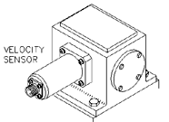
 速度传感器是一种非常流行的传感器或传感器,用于监视旋转机械的振动。这种类型的振动传感器很容易安装在机器上,并且其成本通常低于其他传感器。由于这两个原因,这种类型的传感器非常适合通用机器应用。速度传感器已在旋转机器上用作振动传感器很长时间了,如今它们仍在多种应用中使用。速度传感器具有多种不同的物理配置和输出灵敏度。
操作理论
当导线的线圈通过磁场移动时,会在线圈的两端导线之间感应出电压。感应电压是由能量从磁体的磁通场到线圈的传递引起的。当线圈因振动而被迫通过磁场时,会产生代表振动的电压信号。
信号约定
由振动运动产生的速度信号通常本质上是正弦的。 换句话说,在一个振动周期中,信号在一个周期中两次达到最大值。 第二最大值的大小等于第一最大值,但是方向相反。 根据定义,只能在一个方向上测量速度。 因此,速度测量值通常以零到峰值的RMS单位表示。 RMS单位可以在永久性监视器安装中指定,以允许与从便携式数据收集器收集的信息相关。
要考虑的另一种约定是,朝向速度传感器底部的运动将产生正向输出信号。 换句话说,如果将换能器保持在其敏感轴上并且轻敲底座,则在最初轻敲时输出信号将为正。
施工
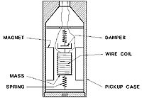
传感器结构速度传感器是一种自发电传感器,不需要外部设备即可产生振动信号。这种类型的传感器由三部分组成:永磁体,金属丝线圈和用于金属丝线圈的弹簧支撑。拾音器中充满了油以减轻弹簧作用。
由于重力的作用,速度传感器在水平或垂直轴安装方面的制造方式有所不同。考虑到这一点,在将这些传感器应用于旋转机械时,必须考虑速度传感器的敏感轴。速度传感器也容易受到横轴振动的影响,如果振动过大,可能会损坏速度传感器。
将线材缠绕到空心线轴上以形成线材线圈。有时,绕线线圈会反向缠绕(绕一个方向,然后沿相反方向缠绕)以抵消外部电场。线轴由薄的扁平弹簧支撑,可将其准确地定位在永磁体的磁场中。
特别注意事项
传感器数量
所有振动传感器均沿其主轴测量运动。在选择传感器数量时应考虑这一事实。由于机壳的结构不对称,三个运动轴上的振动信号可能会有所不同。如果可行,应在垂直,水平和轴向平面上安装速度传感器,以测量三个方向的振动。这三个传感器将提供振动信号的完整定义。
安装
为了获得最佳的频率响应,安装位置必须平坦,并且比速度传感器大10%,或者如果使用单独的安装外壳,则安装位置必须要比速度传感器大10%。需要对表面进行钻孔和攻丝以适应传感器的安装。
灵敏度
在旋转机械应用中,某些速度传感器在所有振动传感器中具有最高的输出灵敏度。灵敏度因制造商而异。在感应电噪声成为问题的情况下,较高的输出灵敏度很有用。对于给定的振动水平,较大的信号受噪声水平的影响较小。下面列出了一些具有灵敏度的速度传感器:
灵敏度
STI CMCPWIL793V 100毫伏/英寸/秒
频率响应
根据制造商的不同,速度传感器的频率响应也不同。但是,大多数拾音器的频率响应范围为10至1000 hz。在为旋转机械应用选择速度传感器时,这是一个重要的考虑因素。拾音器的频率响应必须在机器的预期振动频率范围内。由于线轴的支撑弹簧,在频率响应曲线的下端会发生自然的机械共振。传感器中包含的油或通过线圈导线两端的分流电阻器可抑制这种共振。
校准
无需对速度传感器进行校准,但是每年应将传感器从服务中删除以进行校准验证。需要进行验证,因为速度传感器是唯一具有内部运动部件而容易遭受疲劳破坏的工业振动传感器。
该验证应包括灵敏度响应与频率测试。该测试将确定内部弹簧和阻尼系统是否由于热和振动而退化。该测试应使用能够进行可变幅度和频率测试的振动台进行。
仪表线
下表是应用于仪器现场接线的Belden®电缆的部分列表。这些部件号可能与其他制造商的等效电缆交叉引用。列出的电缆是聚乙烯绝缘的,双绞的,带Beldfoil屏蔽层,排扰线和PVC护套。
Belden®零件编号
零件号外径
18 AWG 8760 0.22英寸
20 AWG 8762 0.20英寸
22 AWG 8761 0.18英寸
公共点接地
为防止接地环路产生系统噪声,必须仅在一个位置将系统公共,接地和仪器导线屏蔽层接地。在大多数情况下,建议在Monitor位置连接公共端,接地和屏蔽层。这意味着所有公共,接地和屏蔽必须在机器上悬空或未连接。
有时,由于安装方法的原因,仪表线的屏蔽层在机壳处而不是在显示器处接地。在这种情况下,所有仪表线的屏蔽层都必须悬空或未在监视器上连接。
导管
所有安装中均应提供专用的刚性导管,以保护机械和噪音。导管应为金属,并与每个段直接接触。所有金属接线盒和配件应与导管直接接触。通过这种类型的安装,可以建立单个接地点。
为了便于卸下速度传感器,应在传感器附近放置一个带有隔离端子条的接线盒。刚性导管应连接到接线盒,而拾音器的最终导管可以是金属挠性导管。
速度提取清单
1.速度传感器类型
2.传感器数量
3.灵敏度
4.频率范围
5.正确的仪表线
6.刚性导管
7.接地线
8.记录的位置
9.校准检查
Velocity Transducer Installation
 The velocity pickup is a very popular transducer or sensor for monitoring the vibration of rotating machinery. This type of vibration transducer installs easily on machines, and generally costs less than other sensors. For these two reasons, this type of transducer is ideal for general purpose machine applications. Velocity pickups have been used as vibration transducers on rotating machines for a very long time, and they are still utilized for a variety of applications today. Velocity pickups are available in many different physical configurations and output sensitivities.
Theory of Operation
When a coil of wire is moved through a magnetic field, a voltage is induced across the end wires of the coil. The induced voltage is caused by the transferring of energy from the flux field of the magnet to the wire coil. As the coil is forced through the magnetic field by vibratory motion, a voltage signal representing the vibration is produced.
Signal Conventions
A velocity signal produced by vibratory motion is normally sinusoidal in nature. In other words, in one cycle of vibration, the signal reaches a maximum value twice in one cycle. The second maximum value is equal in magnitude to the first maximum value, but opposite in direction. By definition velocity can be measured in only one direction. Therefore, velocity measurements are typically expressed in zero to peak, RMS units. RMS units may be specified on permanent monitor installations to allow correlation with information gathered from portable data collectors.
Another convention to consider is that motion towards the bottom of a velocity transducer will generate a positive going output signal. In other words, if the transducer is held in its sensitive axis and the base is tapped, the output signal will go positive when it is initially tapped.
 The velocity pickup is a self-generating sensor requiring no external devices to produce a vibration signal. This type of sensor is made up of three components: a permanent magnet, a coil of wire, and spring supports for the coil of wire. The pickup is filled with an oil to dampen the spring action.
Due to gravity forces, velocity transducers are manufactured differently for horizontal or vertical axis mounting. With this in mind, the velocity sensor will have a sensitive axis that must be considered when applying these sensors to rotating machinery. Velocity sensors are also susceptible to cross axis vibration, which if great enough may damage a velocity sensor.
Wire is wound onto a hollow bobbin to form the wire coil. Sometimes, the wire coil is counter wound (wound one direction and then in the opposite direction) to counteract external electrical fields. The bobbin is supported by thin, flat springs to position it accurately in the permanent magnet’s field.
Special Considerations
Number of Sensors
All vibration sensors measure motion along their major axis. This fact should be considered in choosing the number of sensors. Due to the structural asymmetry of machine cases, the vibration signals in the three axes of motion may differ. Where practical, a velocity sensor should be mounted in the vertical, horizontal, and axial planes to measure vibration in the three directions. The three sensors will provide a complete definition of the vibration signature.
Mounting
For the best frequency response, the mounting location must be flat and 10% larger than the velocity pickup, or if used a separate mounting enclosure. The surface will require drilling and tapping to accommodate the mounting of the sensor.
Sensitivity
Some velocity pickups have the highest output sensitivities of any vibration pickup for rotating machine applications. The sensitivity will vary from manufacturer to manufacturer. The higher output sensitivity is useful in situations where induced electrical noise is a problem. The larger signal for a given vibration level will be less influenced by the noise level. Some velocity pickups with their sensitivities are listed below:
| Sensitivity | |
| STI CMCPWIL793V | 100 mv/in/sec |
Frequency Response
Velocity pickups will have differing frequency responses depending on the manufacturer. However, most pickups have a frequency response range in the order of 10 to 1000 hz. This is an important consideration when selecting a velocity pickup for a rotating machine application. The pickup’s frequency response must be within the expected vibration frequencies of the machine. Due to the support spring for the bobbin, a natural mechanical resonance occurs at the low end of the frequency response curve. This resonance is either damped by the oil contained within the sensor, or with a shunt resistor across the coil’s leads.
Calibration
No calibration of the velocity pickup is necessary, however, on an annual basis the sensor should be removed from service for a calibration verification. Verification is required because velocity pickups are the only industrial vibration sensor which has internal moving parts that are subject to fatigue failure.
This verification should include a sensitivity response versus frequency test. This test will determine if the internal springs and damping system have degraded due to heat and vibration. This test should be conducted with a shake table capable of variable amplitude and frequency testing.
Instrument Wire
The following table is a partial list of Belden® Cables that should be used for the instrument field wiring. These part numbers may be cross referenced to equivalent cables from other manufacturers. The listed cables are polyethylene insulated, twisted, with Beldfoil shield, drain wire, and PVC jacket.
| Belden® Part Numbers | |
| P/N | Nom. O.D. |
| 18 AWG | 8760 0.22″ |
| 20 AWG | 8762 0.20″ |
| 22 AWG | 8761 0.18″ |
Common Point Grounding
To prevent Ground Loops from creating system noise, system common, ground and instrument wire shield must be connected to ground at one location only. In most cases, the recommendation is to connect commons, grounds and shields at the Monitor location. This means that all commons, grounds, and shields must be floated or not connected at the machine.
Occasionally, due to installation methods, instrument wire shields are connected to ground at the machine case and not at the monitor. In this case, all of the instrument wire shields must be floated or not connected at the monitor.
Conduit
Dedicated rigid conduit should be provided in all installations for mechanical and noise protection. The conduit should be metal, and in direct contact with each segment. All metal junction boxes and fittings should be in direct contact with the conduit. With this type of installation, a single ground point can be established.
To facilitate removal of the velocity pickup, a junction box with a barrier terminal strip should be located close to the transducer. The rigid conduit should be attached to the junction box and the final run to the pickup can be metal flexible conduit.
Velocity Pickup Checklist
- Velocity Sensor Type
- Number of Sensors
- Sensitivity
- Frequency Range
- Correct Instrument Wire
- Rigid Conduit
- Grounding
- Location(s) Documented
- Calibration Check